Quick answer
A Buchholz relay and a pressure-relief device are separate protection decisions in an oil-immersed transformer RFQ. First state whether the offered transformer uses a conservator arrangement or a sealed tank. Then define which gas, oil-flow, pressure, alarm and trip functions are required, how contacts terminate, what auxiliary supply is used, and which tests prove operation. Do not accept “transformer protection included” as a complete scope: the supplier should identify the actual device, applicability, set-point responsibility, wiring boundary and FAT evidence for the quoted construction.
Start with the oil-preservation arrangement
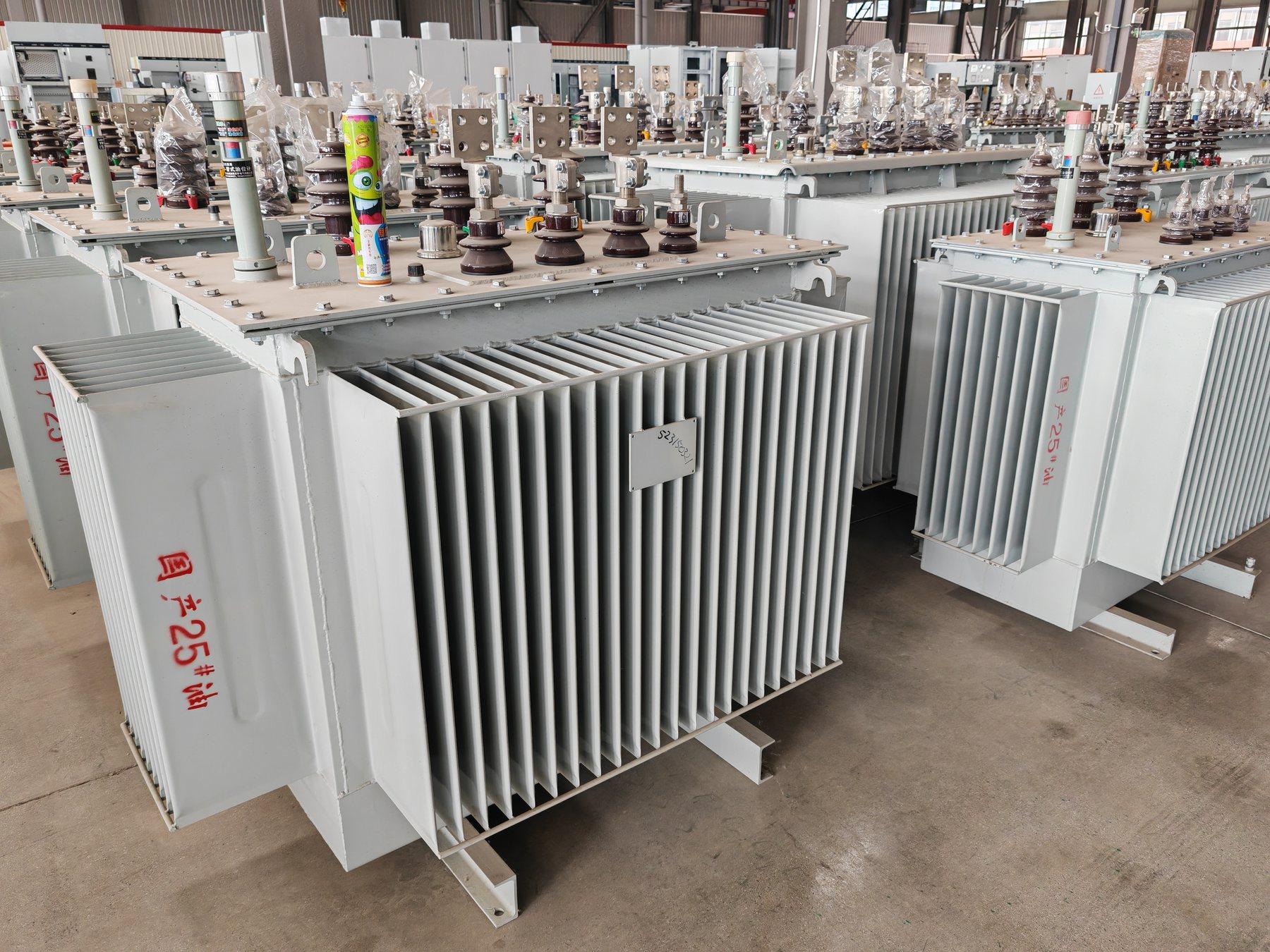
The oil-immersed transformer product family covers more than one project configuration. The conservator or sealed-tank guide explains why the preservation arrangement changes the tank, expansion space, pressure protection, oil-level indication and drawings. A gas-actuated relay is normally considered in a conservator-type oil path, while a sealed-tank design may require a different protection arrangement. The point for procurement is simple: the RFQ must name the intended arrangement or leave it as an explicit engineering decision for the offered design.
The relay, pressure device, oil-level indicator and temperature indicator should not be merged into one generic “accessories” line. Each has a different purpose, mounting point, signal, test method and maintenance requirement. Ask Jinxing to mark the applicability of each item on the accessory schedule and general arrangement drawing.
Separate the device functions before comparing quotations
| Protection or interface | Buyer decision to record | Evidence to request |
|---|---|---|
| Gas-actuated relay | Is a relay applicable to the selected preservation and tank arrangement? What alarm and trip states are required? | Approved protection narrative, device data sheet and wiring diagram |
| Gas or oil-flow indication | Should gas accumulation, oil movement or both create an alarm or trip? | Cause-and-effect schedule and contact allocation |
| Pressure-relief device | Is the requirement relief, alarm, trip, visual indication or a combination? | Tank drawing, relief-device data and test/setting responsibility |
| Oil-level indication | Is the device local only, alarmed, or connected to remote monitoring? | Indicator/contact schedule and terminal plan |
| Temperature protection | Which oil or winding value has alarm and trip thresholds? | Sensor/indicator schedule and protection logic |
| Contact boundary | Where do device contacts terminate, and who supplies the field cable? | Marshalling terminal plan, gland details and cable schedule |
| Acceptance evidence | Which operations are witnessed at the factory and repeated on site? | FAT procedure, simulated-input record and SAT loop plan |
This table is a quotation comparison framework, not a default Jinxing configuration. The final device set depends on rating, construction, project protection philosophy and the owner’s approval documents.
Define alarm, trip and failure behaviour
Write the required state for every contact. Identify normally open or normally closed form, normal healthy state, alarm state, trip state, reset or latch behaviour and the receiving system. If a relay or pressure device is unavailable for the proposed model, require a marked deviation rather than allowing the item to disappear from the offer.
A local pointer, a dry contact in a marshalling box and a signal delivered through a communication gateway are three different deliverables. The oil transformer alarm and remote-monitoring scope guide explains how to turn each signal into a point list with a stable tag, terminal, cable owner and test responsibility. Use that approach for gas and pressure devices as well. State whether the trip contact operates the transformer feeder, an upstream breaker, an alarm panel or only a remote indication; the supplier should not infer the cause-and-effect response.
Coordinate drawings, tank details and maintenance access
Ask for a general arrangement showing the relay or pressure device location, pipe or flange direction, isolation provisions where applicable, visible indication, access for inspection and the route to the terminal box. Cross-check the arrangement with the oil-immersed transformer accessories checklist and the installation plan. Do not approve a device from a catalogue image alone: confirm the offered model, mounting detail, contact rating and project drawing revision.
If the transformer is installed outdoors or in a compact substation, record the environmental exposure, access limitations and drainage or containment interfaces. These conditions can affect inspection and cabling even when the transformer electrical rating is unchanged. Final pressure values, gas relay settings, relief capacity, insulation coordination and protection coordination require the project engineer’s written confirmation.
Make FAT and SAT prove the same points
The transformer factory acceptance test checklist can support the inspection plan. Add device-specific checks: terminal identification, contact continuity, simulated alarm and trip states, mechanical indication, wiring insulation where applicable, and document revision. Factory simulation proves the supplied device and terminals; it does not prove the installed cable, remote I/O, breaker action or owner alarm graphics. Reserve separate site loop and integrated trip tests for SAT.
Request the final data sheet, protection narrative, cause-and-effect schedule, GA drawing, wiring diagram, terminal plan, test procedure, calibration or setting information where applicable, spare-parts list and as-built documents. Keep open deviations visible before manufacturing release.
RFQ checklist
Send these items with an oil-immersed transformer enquiry:
- Voltage ratio, capacity, frequency, phase, impedance, quantity and duty.
- Conservator or sealed-tank requirement, cooling method and installation environment.
- Required gas-actuated relay applicability and alarm/trip functions.
- Pressure-relief device type or performance requirement, indication and contact scope.
- Oil-level and temperature indication, alarm and trip requirements.
- Contact form, normal state, reset/latch behaviour and cause-and-effect response.
- Marshalling box, terminals, glands, auxiliary supply, field cable and receiving-system boundary.
- GA, tank, piping or mounting, wiring, terminal, point-list and protection documents.
- FAT simulations, witnessed operations, SAT loop checks, integrated trip tests and exclusions.
- Spare devices, settings, manuals, as-built drawings and unresolved deviations.
Use the transformer quotation page and project enquiry page to send a marked protection schedule. Jinxing should confirm the actual relay, pressure device, contacts, ratings, tests and delivery scope in writing for the selected model.
FAQ
Is a Buchholz relay included automatically with an oil transformer?
No. Applicability depends on the preservation and tank arrangement, and the quotation must identify the offered device, contacts, mounting and tests. Ask for a marked accessory and protection schedule.
Is a pressure-relief device the same as a Buchholz relay?
No. They respond to different physical conditions and sit at different points in the protection scheme. Define each function, alarm or trip response, wiring boundary and acceptance test separately.
Can a factory contact test prove the transformer protection is accepted?
It proves the supplied device and terminals when the agreed simulation is completed. Site cables, remote I/O, breaker action and owner alarm logic need their own loop and integrated tests.