Quick answer
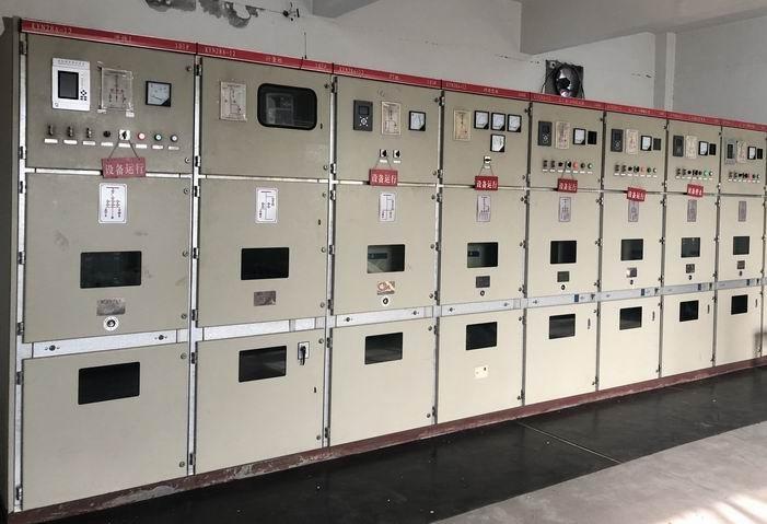
A medium-voltage switchgear bus coupler is a controlled connection between two bus sections. A tender should define when the coupler may close, which incomers can feed it, the normal-open or normal-closed operating state, short-circuit duty, protection and metering, control power, mechanical and electrical interlocks, cable and relay interfaces, and the tests and drawings required for approval. “Bus coupler included” is not enough to compare two switchgear offers.
Start with the operating philosophy
A bus coupler can support transfer, maintenance isolation or another defined arrangement, but the acceptable sequence comes from the project single-line diagram and protection study. Write the normal state first: two bus sections may be supplied separately with the coupler open, or one source may be designated as standby. Do not let a quotation assume a main-tie-main sequence that the owner has not approved.
State the applicable project standard and edition in the tender, together with the rated voltage range, installation conditions and test evidence required for the quoted assembly. A standard reference does not prove that a particular panel arrangement, certificate or report covers every project; verify the actual Jinxing design and test scope in the offer.
Define the panel and lineup boundary
State whether the bus coupler is a complete withdrawable or fixed functional unit, a dedicated panel, a busbar link, or another arrangement. Align the one-line diagram, general arrangement and panel schedule so that the same equipment appears in each document.
| Scope item | Buyer decision | Evidence to request |
|---|---|---|
| Bus sections | Which incomer, feeder and transformer circuits connect to each section? | Approved single-line diagram and panel schedule |
| Coupler device | Circuit breaker, load-break switch, isolator or another device? | Functional schematic, ratings and device data sheet |
| Busbar path | Which conductors, joints and barriers remain live when one section is isolated? | Busbar arrangement, clearances and compartment drawings |
| Operation | Normally open, normally closed, transfer-only or maintenance use? | Operating narrative and cause-and-effect schedule |
| Physical lineup | Panel width, cable entry, lifting, access and future extension? | General arrangement and room interface drawing |
| Accessories | CT/VT, protection relay, voltage presence, earthing switch, shutters and interlocks? | Accessory schedule with included/optional status |
Use the custom MV switchgear RFQ guide to prepare the common project inputs, then keep the bus coupler as its own line in the bid schedule.
Treat interlocks as a safety and availability decision
The coupler must not close under every possible combination of incomers. The owner and protection engineer should define a permissive matrix covering source availability, breaker and earthing-switch position, synchronism or dead-bus conditions, and trip or block signals. The exact logic depends on the network and local rules.
Show each permissive and trip path in a cause-and-effect table. Identify whether it is mechanical, electrical, hardwired, relay logic or supervisory control. The switchgear interlocking cause-and-effect guide can help structure the review. A statement such as “mechanically interlocked” should be expanded into the operations that are prevented and the proof used during FAT.
Align ratings, protection and metering
The bus coupler sees the duty created by both bus sections and the transfer scenario, not only normal feeder current. Ask the responsible engineer to confirm rated voltage, continuous current, short-time and peak withstand, breaking and making duty, insulation level, frequency, altitude and service conditions. Do not copy an incomer rating without checking the coupler’s actual switching and fault duty.
Protection and measurement need the same baseline. Confirm whether the coupler has CTs, VTs, a protection relay, bus-zone or interlocking inputs, synchronism check, voltage presence indication, event recording and trip circuit supervision. If the coupler is not intended to interrupt a fault, say what protection trips the incomers and how the coupler is blocked. A relay model alone does not define the required settings, CT class or point list.
| Review question | Commercial consequence |
|---|---|
| Does the coupler interrupt or only isolate? | The switching device, protection and test scope can change. |
| Can both sources be closed together? | Synchronism, reverse-power, protection and operating rules may be required. |
| Are CT/VT cores dedicated to protection or metering? | The instrument-transformer schedule and relay wiring must match the study. |
| Is control power duplicated or backed up? | Transfer availability and trip reliability depend on the auxiliary supply design. |
| Is future extension required? | Busbar, spare panel space and cable access must be reserved in the current lineup. |
Make control power and signals explicit
List the control voltage, trip and close coils, anti-pumping, local/remote selector, breaker position, spring or mechanism status, interlock healthy, protection trip, bus live/dead and communication healthy signals. State who supplies the DC system, fuses, terminal blocks, RTU, gateway and network test. A mechanically complete panel can still lack the control-power or SCADA interfaces needed by the site.
Set the FAT and SAT boundary before comparing price. Ask for wiring, mechanical operation, interlock, relay or functional, trip/close and communication point-to-point checks, plus a final as-built point list. Request the type-test and routine-test scope for the quoted assembly; one sample report should not be assumed to cover every lineup or rating.
RFQ checklist
Provide:
- Approved single-line diagram with source, transformer, feeder, bus-section and normal operating states.
- Rated voltage, current, frequency, fault level, short-time duration, altitude and installation environment.
- Coupler device type, interrupting duty, earthing switch and shutter requirements.
- Incomer and coupler interlock matrix, transfer narrative, trip logic and synchronism or dead-bus requirements if applicable.
- CT/VT ratios, cores, accuracy, burden, relay functions, metering and event-recording needs.
- Control-power source, auxiliary voltage, terminal schedule, RTU/protocol and cable entry responsibility.
- Panel arrangement, room dimensions, access, lifting, cable trench, future extension and shipping constraints.
- Drawings, calculations, test plans, certificates or reports, packing documents and destination requirements.
- Quantity, project stage, delivery target and the information still open for engineering confirmation.
For the commercial path, review the Medium-Voltage Switchgear page and send the final schedule through Request a Quote. The actual bus coupler configuration, ratings, protection, interlocks and documents remain project-specific.
FAQ
Is a bus coupler the same as a busbar isolator?
No. A coupler arrangement may include a switching device, protection, control, metering and interlocks that allow a defined operating sequence. An isolator or busbar link may have a different switching and fault-clearing duty. Use the single-line diagram and operating narrative to define the required function.
Can the bus coupler be left as a future spare panel?
Only if the buyer accepts the future interface risk. Reserving a panel position may require busbar joints, shutters, cable access, protection provisions, control wiring and room space today. Record whether the tender requires a complete coupler, a tested future extension point or only civil and busbar allowance.
What should be checked during FAT?
Check the delivered device and wiring against the approved drawings, operate each mechanical and electrical interlock, verify trip and close circuits, test protection and metering functions as applicable, confirm control-power behavior, and record the final terminal and signal list. The exact test sequence follows the project specification and quoted assembly.