Quick answer
Specify the neutral and protective-conductor arrangement as part of the low-voltage switchgear scope. State the system earthing method, whether neutral and PE or PEN remain combined or separate, expected neutral duty, bar dimensions and connections, incoming and outgoing cable interfaces, metering needs, bonding, access and test records. The exact arrangement must follow the project design and applicable local rules; it should not be inferred from the cabinet name alone.
Why neutral and PE scope changes the offer
A low-voltage switchboard can serve three-phase four-wire distribution, motor control, generator transfer, transformer secondary distribution or mixed commercial loads. Those duties can require different neutral, protective-conductor, bonding, metering and cable-entry arrangements. Harmonic loads, unbalanced loads, multiple sources and maintenance isolation can also change what the design team must review.
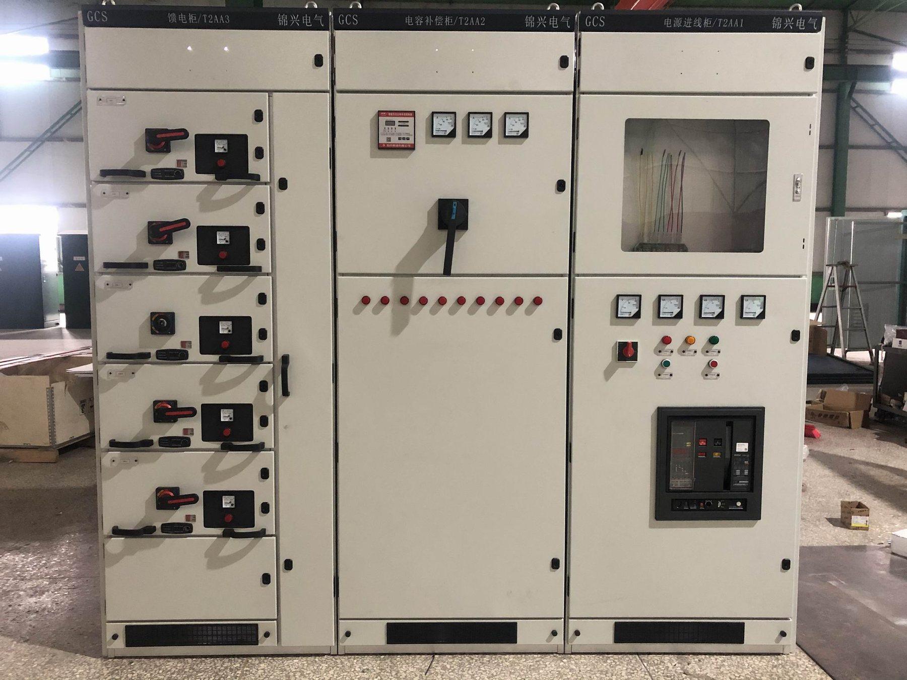
A quotation that lists only the number of feeders may omit the bars and interfaces needed to complete the installation. Identify the Jinxing low-voltage-switchgear product family, then put the neutral and PE/PEN decisions into the same panel schedule as the incomer and feeder devices.
Define the electrical arrangement before pricing
| Decision area | Buyer input to record | Evidence to request |
|---|---|---|
| System earthing | Earthing arrangement, source bonding point and local authority requirements | Approved single-line and earthing diagram |
| Neutral conductor | Required neutral duty, continuity, sizing basis and switching philosophy | Datasheet, busbar schedule and wiring diagram |
| PE or PEN | Where protective and neutral functions are combined or separated | Earthing/bonding drawing and terminal schedule |
| Source interfaces | Transformer, generator, UPS or parallel-source connections | Source interface matrix and interlock narrative |
| Feeder interfaces | Three-pole/four-pole devices, cable cores, glands and termination space | Feeder schedule, cable plan and terminal drawing |
| Metering | CTs, neutral sensing, meter reference, test links and access | Metering schedule and point list |
| Future scope | Spare bar capacity, terminals, links and access for later feeders | Future-extension schedule and GA drawing |
The table is a procurement framework, not a default design. Have the project engineer confirm the system arrangement and the supplier show exactly where each conductor terminates.
Separate neutral, PE and PEN responsibilities
Record the source point where bonding is allowed, the locations where neutral and protective conductors must remain separate, and the terminals or bars supplied inside the cabinet. Do not leave the installer to decide this from a generic wiring diagram. The cabinet drawing, site earthing drawing and incoming cable schedule should use the same labels.
If a project uses a combined conductor at one boundary and separate conductors downstream, show that transition and its access requirements. If the switchboard is part of a generator or transfer system, identify which source controls neutral switching and how the protective conductor remains continuous. The final solution depends on the project engineer, utility or owner rules and the offered assembly.
The existing LV panel neutral sizing guide focuses on current and harmonic-load questions. This article covers the procurement boundary: bars, bonding, separation, terminals, metering and proof that the quoted cabinet matches the approved system.
Connect bars to cable and metering details
Neutral and PE decisions affect physical layout. Confirm bar location, access, short-circuit duty, joints, supports, cable lugs, gland plates, segregation, test links and spare terminals. For metering or protection, state whether neutral sensing, residual-current measurement, CT secondary terminals or other project inputs are required. Do not assume that a meter or breaker accessory automatically provides the required neutral or protective-conductor path.
Use the LV panel cable-entry and termination guide to coordinate incoming and outgoing cable space. Request a marked GA drawing showing bar positions, entry direction, termination height, removable covers and maintenance access. A physically adequate bar can still fail the project interface if the cable route or test point is inaccessible.
Make verification and handover explicit
Ask for a document register that links the panel schedule, earthing drawing, busbar schedule, wiring diagram, test plan and final as-built records. The inspection should verify labels, joints, continuity, insulation where applicable, protective-conductor connections, neutral links, metering terminals and device operation against the approved documents. The low-voltage switchgear testing guide can support the broader test plan, while this article identifies the conductor-specific checks.
Do not treat a routine report for another arrangement as proof for the offered cabinet. Ask the supplier to identify the quoted model, configuration, open deviations, applicable evidence and the tests included in FAT or site commissioning.
RFQ checklist
Include the following with the low-voltage switchgear enquiry:
- Single-line and earthing diagrams showing source, bonding point, neutral and PE/PEN transitions.
- System voltage, frequency, fault level, source types, parallel operation and transfer philosophy.
- Neutral duty, expected imbalance or harmonic context, switching requirement and termination method.
- PE or PEN bar location, bonding links, earth terminals, enclosure connections and continuity expectations.
- Incomer and feeder device poles, cable cores, lug sizes, gland plates, entry direction and spare terminals.
- CTs, metering, neutral sensing, test links, protection interfaces and signal ownership.
- Busbar supports, joints, access, segregation, maintenance and future-extension requirements.
- GA, busbar, earthing, wiring, terminal, inspection, FAT, SAT and final as-built documents.
- Quantity, destination, project stage, applicable owner rules and unresolved engineering decisions.
Review the low-voltage switchgear product family and submit the marked schedule through Request a Quote. Final conductor arrangement, ratings and test scope remain project-specific.
FAQ
Is the neutral bar always the same size as the phase bars?
Not necessarily. The required duty depends on the load profile, imbalance, harmonics, system arrangement and project calculation. Ask the engineer to provide the design basis and the supplier to show the quoted busbar schedule.
Can the neutral and PE bars be combined inside the cabinet?
Only where the project earthing design and applicable rules permit that arrangement. Record the bonding point and any transition to separate conductors on the approved drawings; do not leave it as an installation assumption.
What should be tested before energizing the panel?
Verify the approved labels and connections, protective-conductor continuity, neutral links, insulation and functional circuits as applicable, metering or sensing terminals, and the operating sequence. The exact tests and acceptance limits must follow the project specification and quoted assembly.