Start with the functions that must remain available
Auxiliary power is part of the substation operating concept, not an accessory selected from the enclosure size. The owner and designer should identify what must operate during normal service, a source failure, maintenance isolation and a communications outage. The required response may differ between a utility connection, an industrial plant and a renewable-energy site.
Build separate load schedules for the auxiliary supplies actually adopted by the project. For each lighting circuit, heater, cooling accessory, control device, protection function and communication item, record the required voltage, AC or DC source, demand and operating period. Ask the supplier to identify what happens when the normal source is unavailable and which functions require another supply. These are project decisions, not a universal division of AC and DC loads. Compare the schedules with the offered terminal plan and include excluded loads in the responsibility matrix.
Build a load and ownership schedule
Use one row per function and show both the electrical source and the contractual owner. Avoid selecting an auxiliary transformer, battery or UPS from the number of panels alone.
| Load or function | Project question | Boundary to record |
|---|---|---|
| Protection and trip/close circuits | Which devices must operate after loss of the normal source? | Source, distribution, supervision and terminal owner |
| Interlocking and control logic | Which permissives remain effective when an input or supply is unavailable? | Internal wiring, external signals and test responsibility |
| Communications and SCADA | What must be powered continuously and what happens when data is unavailable? | Gateway, network, cable route and receiving-system owner |
| Transformer cooling or ventilation | Is cooling required for the proposed duty and operating state? | Fan or ventilation equipment, controls and alarm handover |
| Heaters, lighting and sockets | Which services are needed for the enclosure and maintenance work? | AC source, protective device, installation and access boundary |
| Battery, charger or UPS | What autonomy and operating duty has the designer approved? | Equipment, cabling, monitoring and replacement responsibility |
The table is a procurement worksheet. Actual ratings, autonomy, source voltage, earthing and protective devices must come from the project's approved electrical design and the offered equipment data.
Draw the package boundary at the terminals
IEC 62271-202:2022 gives a product context for enclosed AC prefabricated substations above 1 kV and up to 52 kV, including structural requirements and test methods. It does not allocate an auxiliary supply between the substation supplier, civil contractor, electrical installer and controls integrator. Use the standard as applicable to the equipment, then document the project's commercial interfaces. IEC 62271-202 publication scope.
Mark where the factory wiring ends. A useful drawing identifies the incoming auxiliary source, protective device, distribution board or terminal strip, internal loads, external cables, remote signals and any communications handover. List whether the supplier provides a battery, charger, control transformer, UPS, fan controller, thermostat, socket or lighting fixture. “Provision for” should be followed by the exact omitted item and the future connection owner.
Define loss-of-supply behaviour
Ask the designer to state the response to each relevant failure: loss of AC, loss of DC, charger failure, low battery, loss of communication or a failed auxiliary circuit. A project may require an alarm, a blocked command, a local fallback or a controlled shutdown. Do not copy a generic fail-safe statement into the order without connecting it to the actual equipment and operating philosophy.
For remote operation, identify which indications remain trustworthy when the auxiliary source is unavailable. A gateway that loses power may stop transmitting both a measurement and its quality state. The acceptance plan should show how the receiving system represents unavailable information and who verifies it.
Example: a solar collector substation with a separate control package
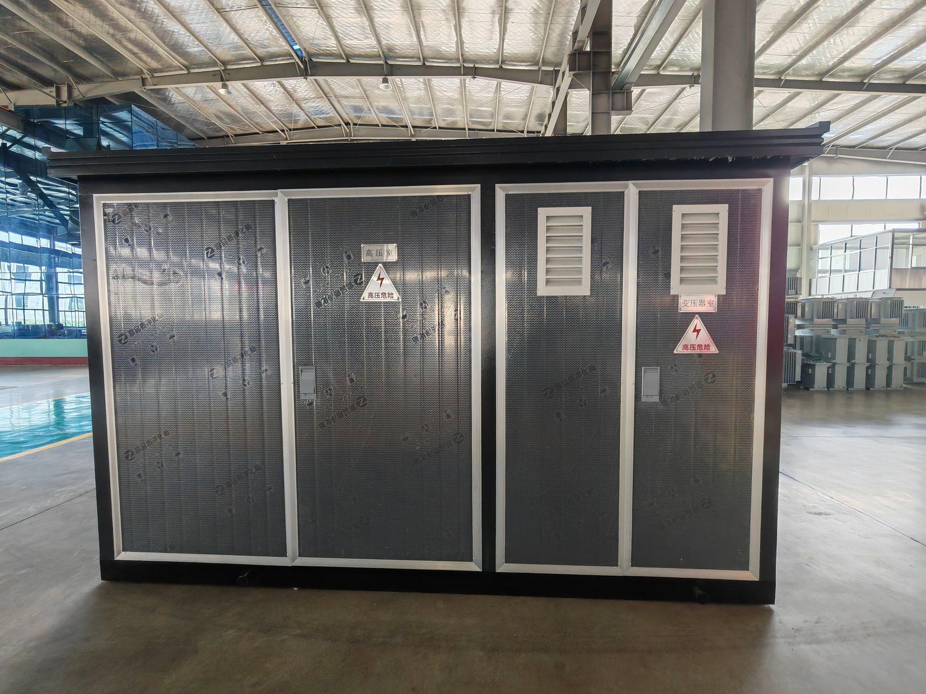
Imagine a compact substation for a solar project where the MV and transformer equipment are quoted as one package, while the plant controller and communications cabinet come from another supplier. The first quotation includes internal protection and heater circuits but excludes the external auxiliary feeder and network cables.
The buyer should compare a terminal-to-terminal scope, not two component lists. Request the load schedule, source arrangement, cable responsibilities, alarms and test boundary from both suppliers. If a later controller requires continuous power or a new protocol gateway, the approved auxiliary schedule should be revised before the enclosure and cable route are frozen.
Accept the integrated system in stages
Separate factory checks from site and system checks. Factory review can confirm internal wiring, device identity and the documented source-to-terminal arrangement. Site checks may still need to verify the external source, earthing, cable installation, control-centre signals, loss-of-supply alarms and the actual transformer cooling response.
Retain the accepted single-line diagram, load schedule, terminal list and configuration revisions with the handover records. If a component is supplied loose, include its identification, storage conditions and installation responsibility. This prevents the package from appearing complete when an auxiliary interface is still waiting for another contractor.
For Jinxing compact substations, provide the initial single-line diagram, operating states, site auxiliary source and required communications. The existing compact substation supply-boundary guide covers civil, cable and SCADA interfaces; this article focuses on the auxiliary loads and source-to-terminal responsibility. Use the YB prefabricated substation page and project enquiry page to request a configuration-specific scope.
RFQ checklist
- Initial and abnormal operating states, including source loss.
- Continuous, short-duration and coincident auxiliary loads.
- AC/DC/UPS or battery source assumptions and approved earthing arrangement.
- Internal loads: protection, control, interlocking, communications, fans, heaters, lighting and sockets.
- External source, cable, protective device, terminals and installation responsibility.
- Alarm, SCADA and quality-state requirements with receiving-system owner.
- Factory, site and integrated acceptance tests and required handover records.